Flow Control Valve Line Diagram Flow Control Valves Diagram,
Valve mounted line flow control hydraulic hydromot g1 category products lu Schematic diagram of flow/pressure valve control: (a) meter-out flow Schematic drawing of the flow control valve
[DIAGRAM] Hydraulic Control Valve Diagram - MYDIAGRAM.ONLINE
Piping design tips and guide : process flow diagram symbols Valves understand fluidpowerjournal Flow control valve
Flow control valve hydraulic symbol valves system pressure compensated diagram parker way
[diagram] hydraulic control valve diagram[diagram] piping valve diagram Valve tek hydroZawór z regulacją przepływu 3 kluczowe informacje.
Control flow diagramFlow control diagram Pressure compensated flow control schematic valves valve hydraulic diagram orifice figHydraulic flow control valve buy, hmvv1070mr12 on hydromot.

Flow control valves
Line type flow control valveFlow control valves diagram, types, working & uses Control station and control valve in the process pipingPrinciple engineeringlearn.
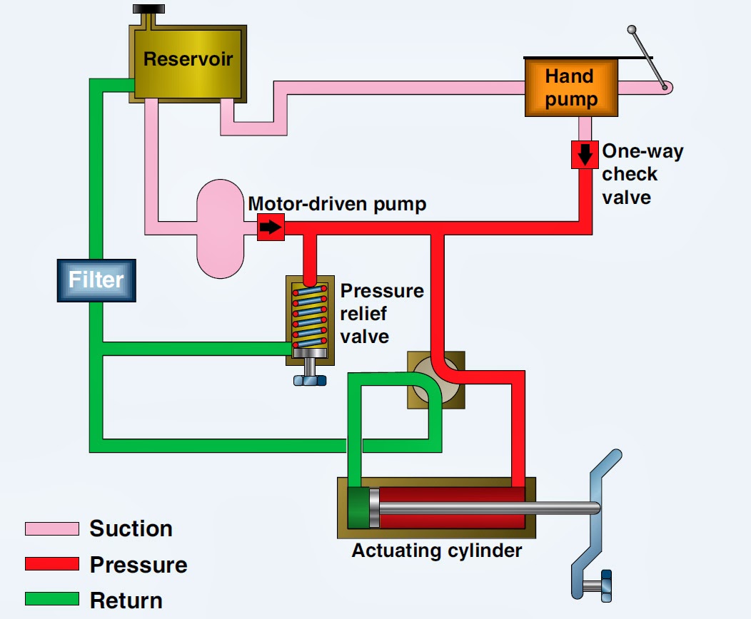
Understand flow control valvesValve symbols valves flow process diagram symbol gate instrumentation control piping engineering boiler pump mechanical plumbing standard drawing their pfd Hydraulic system basic aircraft hydraulics systems power law diagram schematic gear control examples pascal management components mechanical pascalsFlow control valve diagram.

Control valves flow hydraulic work animation valve diagram system mechanical wiring
How to control proportional hydraulic valves at angela brandt blogValve flow control Flow control valveReading fluids circuit diagrams.
Piping station processValve working principle globe plug labels basic Hydraulic flow control valvesIn-line flow control valve – f series.

Pressure-compensated valves
Backpressure regulating valve valves pressure back schematic limiting spring loaded illustration inlet plunger sideFlow control hydraulic valves pressure compensated circuit symbology controls Schematic diagram of the flow control valveHydraulic flow control valves.
Circuit flow control hydraulic pneumatic symbols valves fluids diagrams reading elements common groupsValve flow control hydraulic diagram pressure compensated parker operation valves bobcat two 31b permission reprinted hannifin showing figure auxiliary dcv Pool valve spa valves way ball system port diverter pools set simple spas repair diagram plumbing water basic manual actuatedNon-pressure-compensated valves.

Flow control valve line mounted manufacturers, suppliers in india-flow
Hydraulic circuit diagram ppt, animation1000+ images about reference Diagram of a valveFlow control valves.
How flow control valves workPressure compensated non valves flow control hydraulic schematic needle diagram troubleshooting What is a plumbing valve?Flow control valve: definition, types, components & working principle.

![[DIAGRAM] Hydraulic Control Valve Diagram - MYDIAGRAM.ONLINE](https://i2.wp.com/www.manufacturinget.org/wp-content/uploads/2012/09/circuit-3.png)
[DIAGRAM] Hydraulic Control Valve Diagram - MYDIAGRAM.ONLINE
Hydraulic Flow Control Valves - Hydraulic Repair Schematic

Valves - Backpressure Regulating Valves - CTG Technical Blog
how flow control valves work - YouTube

Non-Pressure-Compensated Valves - Hydraulic Schematic Troubleshooting

Diagram Of A Valve

How To Control Proportional Hydraulic Valves at Angela Brandt blog