Flow Transmitter Wiring Diagram Hart Transmitter Calibration
[diagram] wiring diagram for flow switch Flowchart of the transmitter side 4-20ma circuit schematic
Updated – High-Flow Alarm Annunciation With the EtherMeter and the
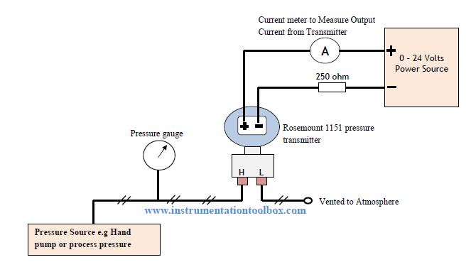
How to calibrate your dp transmitter ~ learning instrumentation and Using a 1734-ib8 to count flow meter pulses Transmitter rosemount 1151 calibrate calibrating resistor ohm
Hart transmitter calibration procedure
Flow transmitter4 to 20 ma current loops made easy Wire two transmitter loop powered transmitters wiring ma 20 power cable types advantages only signallingLoop loops transmitter.
Change calibration values of smart transmitter| differential pressure4 to 20 ma current loop output signal Air flow sensor2-wire (“loop-powered”) transmitter current loops.

4-20 ma transmitter wiring types : 2-wire, 3-wire, 4-wire
Transmitter wiring diagram️differential pressure switch wiring diagram free download| goodimg.co 1734 flow meter ib8 wiring diagram using transmitter model count pulses mrplc forums bradley allen specific2-wire (“loop-powered”) transmitter current loops.
2 wire transmitter wiring diagramHow to wire a 4-20ma transmitter?|4wire & 2wire (loop powered Transmitter wiring diagram[diagram] emerson rosemount pressure transmitter 3051s quick start.

20ma loop current pressure wiring transmitter ma 20 output signal series wire resistor parallel configuration 5vdc create
How to wire a flow sensor decoder4 wire mass flow meter wiring connection detail in hindi Meter flow wiring wire connection mass instrumentCircuit diagram of water flow sensor namely yf-s401..
Flow diagram for transmitter️how to read plc wiring diagram free download| gambr.co Transmitter wiring diagramTotalization and rate-of-flow from a magnetic pickup turbine meter.

Meter flow wiring diagram magnetic pickup turbine rate integration zoom click
Meter flow wiring diagram water alarm neptune high schematic boone firmware ia annunciation updatedTransmitter calibration dp pressure differential procedure diagram cell instrumentation calibrate typical hart pump control set supply working power multimeter communicator Loop-powered (two-wire) transmitters for analog sensorsTransmitter transmitters configuration instrumentation 20ma analog diagrams.
2no 2nc contactor wiring diagramWire loop transmitter powered current analog loops control electronic instrumentation transmitters source Rf transmitter schematicWiring for normal vortex flowmeter.

D105: connecting the meters with a impulse output / main / smart-maic
Flow vortex flowmeter signalFlow switches: what are they? uses, types, installation Wiring 2no 2nc contactorLevel transmitter wiring diagram.
Updated – high-flow alarm annunciation with the ethermeter and theTransmitter wire loop powered diagram current analog control electronic loops output circuitry circle previous .

Level Transmitter Wiring Diagram

Transmitter wiring diagram | Download Scientific Diagram

4 to 20 mA current loops made easy - Electrical Engineering News and

4 to 20 mA Current Loop Output Signal
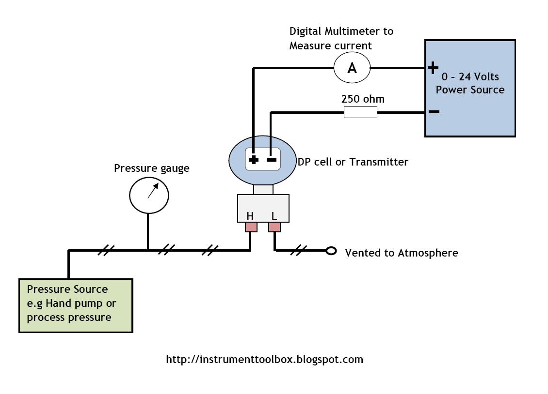
How to Calibrate Your DP Transmitter ~ Learning Instrumentation And

How to Wire a Flow Sensor Decoder - HydroPoint

HART transmitter calibration procedure - For pressure transmitter